Yes, it's a musical. But this is about the stuff that grows out of your skin. A Trichoscope is a microscope for looking at hair.
My friend Ursula brought this item in to our Makerspace. She had brought it with her from Germany when she relocated to England several decades ago. How it got to Germany in the first place will likely remain a mystery. She wondered if it could be rendered useful somehow.
It's an unusual device. It's an illuminated microscope, which is not so unusual. But the lid of the case contains a small projection screen, and there is an eyepiece adaptor which reflects the image from the eyepiece towards the screen. This is rather odd.
However, this is not just any microscope for looking at hair. The back story is nuts. This microscope was a sales and marketing tool for a cosmetics company called 'Redken'.
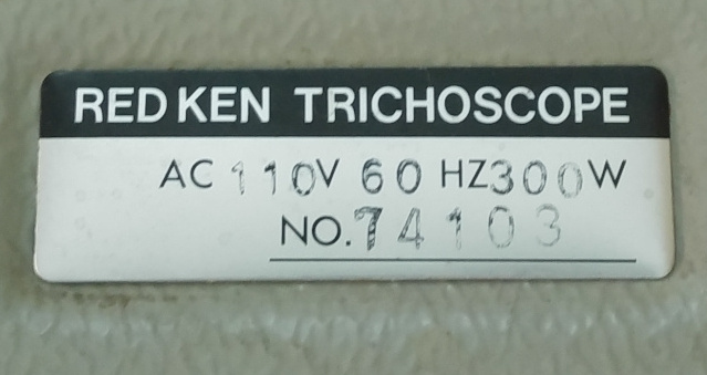
The trademark 'trichoscope' was registered by Redken in 1982 ( https://uspto.report/TM/73388540 ), and it gave the date of first use as March 1973. The inference is that Redken were supplying Trichoscope's in 1973, and there is an intriguing 'number' on Ursula's device :
It seems quite implausible that over seventy four thousand of these devices were actually made, so I'm inclined to guess that this 'No.' represents a date - perhaps it's 1974, device 103.
Who were 'Redken' ? The brand is still in use today. It is owned by L'Oreal, and they market haircare products using it. There's a company timeline on their website, which features an interesting microscope graphic at the '1970' point.
The inference I draw from all this is that these devices were supplied to hairdressers from the early seventies onwards ( end date unknown ), and used by hairdressers to 'diagnose' their customer's hair in the salon, and hence promote Redken products to their customers. This is the reason for the projection screen - so that the operator of the scope could show the customer the parlous state of their hair. I have no view on exactly how valid any of this 'science' might be.
The first technical challenge is evident from the photo above - this device uses US - style power. A lot of power - 300 watts ! I have a 300W 110V 60Hz supply, but could not find a lead that matched the original power socket. In any event, I decided it would be much better if the thing could be adapted to use European power, rather than having to plug in a convertor.
And so a little disassembly was indicated. Whoopee, I like taking things apart 🙂.
I like taking things apart, and I like living to tell the tale. The first discovery was that there was a projector bulb compartment under a cover on the top of the device, with no projector bulb. That was pretty easy I was sure, a 240V halogen projector bulb could surely be found, if that was what I wanted.
The second discovery was that this compartment was lined with white asbestos. This would have seemed totally reasonable in 1973, but somewhat scary in 2021.
To add to the scariness, it was clear that the device contained a substantial centrifugal fan, which would suck air out of the aforementioned asbestos lined compartment, and eject it out of a grille at the rear. And the internals of the thing were dusty - very dusty.
At this point, my self preservation muscle started to twitch. I had donned a mask and gloves as soon as I realised the asbestos was there, but the presence of so much dust coating all the internal components was concerning, even if it was probably 99.99% harmless.
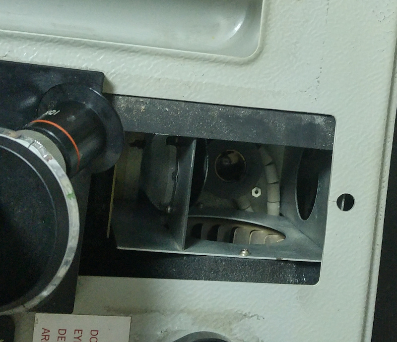
This piccie shows the bulb compartment, with the asbestos lining removed :
Here you can see all the dust/fibre crap lurking inside when the cover is removed :
I decided that there was no reasonable way to safely decontaminate the centrifugal fan, or the transformer/power transistor assembly. The task just did not pass my risk/reward threshold. In any event, this was a 110V system which would require adaptation come what may. So I carefully removed all the aforementioned items, including the asbestos itself, and wrapped this bundle in several plastic bags pending a trip to the dump.
Then I needed to clean the rest of the interior, wearing the aforementioned mask and gloves. This involved a lot of very delicate work with damp kitchen towels, carefully disposed of. To get into the cracks and corners, I used Blu-tack, or coated the area with Copydex and peeled it off.
Here is the optical path, minus a mirror which was attached to the round opening at the rear of the bulb :
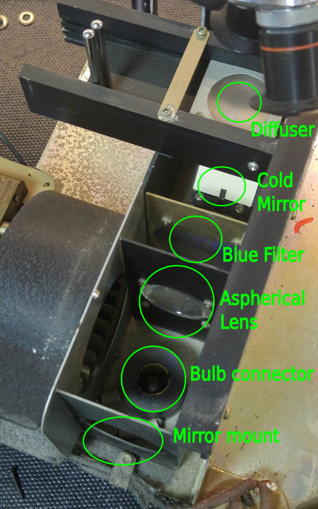
The optical system 'downstream' of the projector bulb was relatively dust free ( the main airflow was in from one side of the bulb compartment and out via the fan on the opposite side ). Plus at this stage I did not want to dispose of optical components until I understood what they were doing, because I might want to use them.
The optical path was interesting. The various components appeared to have three goals. Firstly, to dump heat. Secondly, to correct the colour of the bulb by moving it towards the blue end of the spectrum. Thirdly to focus and collimate the beam such that as much light as possible was sent towards the sample.
The need to dump heat was no big surprise, given that a halogen projector bulb emits ( much ) more energy as infrared than it does as visible light. In general, in a microscope you don't want to toast your sample. So the path from the bulb included a 'cold mirror'.
I had not come across one of these before, and didn't actually realise what it was until quite late in the design, but it is a type of half-silvered mirror which reflects infrared in one direction, and visible light in the opposite direction. In each case the light is deflected by 90 degrees. In this case, the infrared was dumped out of a hole in the bottom of the case, and the visible light was sent upwards to the sample, via polariser, neutral filter, and diffuser.
Upstream of the cold mirror was a blue filter, and upstream of that was an aspherical lens and mirror for collimation purposes.
There appeared to be two fundamentally different approaches to 'restoring' the lighting system. Either attempt to restore it by using a projector bulb and keeping the optical system as is, or change the light source for a modern LED based system and ditch any unnecessary components in the optical path.
The problem with the 'use a projector bulb' approach is that then you still have the infrared issue, which would need a cooling solution. I'd effectively have to replace the centrifugal fan with something equivalent, in addition to adding a new and substantial power supply.
On the other hand, I could try using a ''daylight' COB LED. Because this type of light is not a 'point source', and because the infrared emission is low, most of the optical path components could be ditched. The components would be relatively cheap and compact. The power required would be very much less.
The downside would be the spectrum - LED's do not emit 'black body' radiation, and the spectrum would be peaky and not really much like daylight. Also, it was not entirely clear that such a solution would deliver the necessary light intensity for projection purposes.
After chewing on this for a while, I decided that projection was a would-be-nice. These days, you just would not solve that problem that way - you'd put a digital camera on the eyepiece end, and view the image on a computer. Fundamentally, I was not trying to recreate the 1970's experience, I just wanted to make a useful tool. So I would try the LED approach.
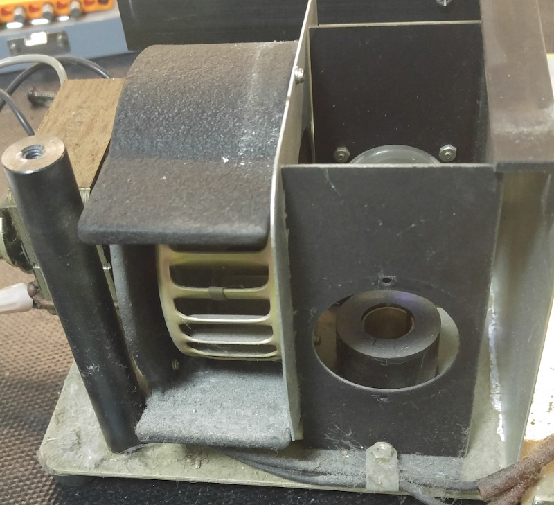
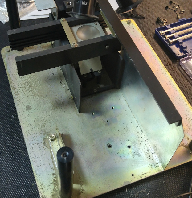
Here is the device with the power supply, fan, and all the optics bar the cold mirror stripped out. At this stage, I was still thinking I would mount the COB device vertically in front of the mirror. There's a lot of space in there :
The first thing I tried doing was to just point a 10W 12V COB spotlight at the cold mirror ( which I didn't realise was a cold mirror at that point ). If this worked, things would be really easy. I would just mount this thing in front of the cold mirror, use an external 12V supply via a simple DC socket, bingo.
Well, close but no cigar. There was probably enough light for normal microscope viewing, but projector viewing was just not quite there. Projector viewing was not critical, but I hated the idea of coming so close and missing. So things got a little more complicated 🙂.
The requirement was to find a way to get more light to the sample. Clearly, just cranking up the power of the light source would help with this.
What I discovered was that higher powered COB devices were available, but that they tended to use power supplies operating at more than 12v. Nonetheless, these were easily available and very compact.
Another realisation was that if I could fit the light in directly beneath the sample stage, I would not need to bounce light off the 45 degree mirror. Bringing the light source closer to the sample stage seemed like a good idea. I thought about typical illuminated microscopes that I had seen, where there was a light directly beneath the stage.
This was the point when I realised that the 45 degree mirror was in fact there for more than one purpose - both redirecting the light required, and dumping the light ( i.e. infrared ) that was not. I figured, without doing much research beyond looking at some emission curves, that an LED system would produce so much less IR that it would not matter if I placed it directly beneath the stage, where the cold mirror currently was.
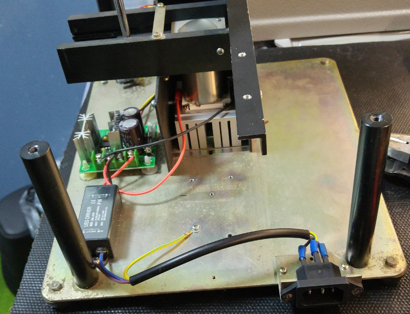
So the new plan was born. I would fit a 20W COB LED directly beneath the stage, and add a suitable power supply to the design. After all, there was no shortage of space - the power supply would be tiny compared to the transformer, power transistors, and snail fan assembly that I had removed.
The original system also had a way of controlling the intensity of the light by altering the current supplied to the halogen bulb via a knob on the top of the case. I wanted to replicate this functionality if I could. But with an LED, I couldn't do it by just tweaking the voltage - LED's have an 'on/off' behaviour built in, you can't just fiddle with the volts or the current and get more or less light.
I knew that LED intensity was typically altered using a PWM ( Pulse Wave Modulation ) technique - basically, by flashing the LED on and off for varying periods of time. The tricky part was finding a PWM controller that would handle the voltage I needed for my 20W COB device. I would also need to fit this device into the case. What I discovered was that PWM devices greater than 12V are actually sold as 'DC Motor Speed Controllers', typically for use with fans. No matter, they are compact, cheap, readily available, and work as expected.
Here is a photo showing the elements of the solution in their positions on the base :
However, there is a little more to say here.
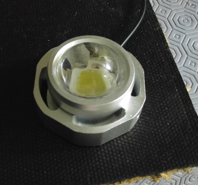
Rather than waste light that was not headed in the direction of the diffuser, I decided to put a crude collimator on top of the LED. This was formed from a piece of thin stainless, wrapped into a roughly cylindrical form so that it wrapped the actual light emitting surface and avoided bumps on the ceramic carrier part of the COB.
I'm afraid I didn't take any piccies of this process, but it was actually quite tricky. This was down to the need to make some reasonably accurate folds in the stainless sheet in order to connect the two ends together. If I were doing this again, I might see if I could purchase stainless tubing of a suitable size. I tacked the collimator to the COB with some dabs of Gorilla glue. I don't know how strong this connection really was, but it was sufficiently strong, which is what counts.
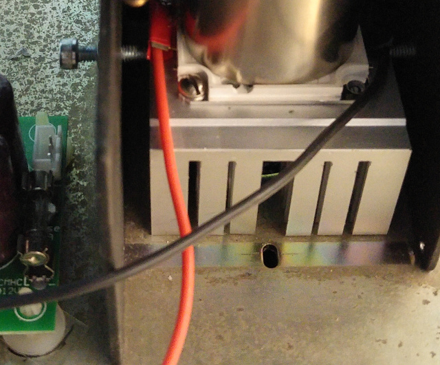
Then I mounted this subassembly on a heatsink. I think I could have gotten away without this. If I'd placed the COB on the baseplate, over the hole that the cold mirror used, I think that would have been just fine from a heat dissipation point of view.
However, the added benefits of the heatsink are firstly that it moves the COB closer to the diffuser, and secondly it allowed me to install it a manner that made it easy to adjust it's position beneath the diffuser. I had to tap a couple of small holes in it to allow the COB to be secured, and a couple of holes in the bits of metal on either side of the heatsink to give me the locating screws. In this way, I get to be able to make X/Y adjustments to the position of the assembly, in case that helps to
Since the heatsink came for free ( just an ancient processor heatsink I had kicking around ), these benefits seemed worth having. :
The original connector for the trichoscope was a 110V AC connector of a form that no longer seems to be standard - it was not a normal 'C' series type. It was mounted on the base via a metal bracket, and then exposed via a hole in the fibreglass cover. Because I needed to supply 240V AC to the LED power supply, getting this socket/bracket right was important.
So that was that 🙂 A Redken Trichoscope rescued from 110V asbestos - laden oblivion, without major change to the outward appearance. I'm pretty sure that this does not count as 'restoration', but that was not the driving principle here. There now exists something useful which was not useful before. I'm happy with that.
© Mark de Roussier 2021, all rights reserved.