I'm not a Dremel fan. In the many years I've owned one, it's been a rare occurrence to find a task that is best done by a Dremel. Add to that the very high price ( and often dubious quality, both of materials and design ) of the accessories that might enable your job to be done, and you may see why Dremels don't feature prominently in my making life.
But, at least with regards to accessories, the advent of 3D printers has triggered a great deal of creativity. There are now hundreds of freely downloadable designs for Dremel gadgets and accessories. You'd think I'd be happy 🙂
Of course, the gadget I want is not amongst these things. This is the story of a thing that I wanted, and therefore made, to hold my Dremel at an angle so that I could use a grindstone to sharpen things.
Ah, well. This starts with a particular knife, the sharpening of which has always been a source of frustration. A part of this knife is recurved. For the non knife geeks, this means there is a concave curve in the edge. Therefore a flat sharpening device cannot reach the edge of the blade.
Of course, there is a solution. The obvious way is to use a cylindrical sharpening device, where the radius of the cylinder is less than the radius of the recurve. There's a related but slightly different approach where the sharpening device is not a cylinder, but a cone. And then there's another twist, where you use a surface curved in more than one dimension - this can get you a blade edge that has a curved profile, aka hollow ground. There is, of course, an infinite amount of YouTube wisdom on this topic, some of says 'you can use a flat stone !'. What they then go on to do is use the edge of a flat stone. i.e. the curved bit. Doh.
The challenge is to be able to apply the sharpening device at as consistent an angle as possible along the length of the blade. This is really hard to do by hand even when the blade is straight. Mostly you get away with it if you're only touching up the edge, but if you want to reset, or maybe even create from scratch, the primary bevel it gets much trickier.
The upshot of all this thinking is that I wanted to mount a grindstone in my Dremel, and fix the Dremel at a suitably chosen angle with respect to a reference surface. I wanted the reference surface to be horizontal, because I think it's easier to handle the blade that way, without needing to factor gravity into the equation along with everything else - so a tilting table would not do, I have to tilt the motor, i.e. the Dremel itself.
The first thought I had was that I could use the screw thread on the end of the Dremel in order to mount it in whatever tilting device I was going to make. This is a normal approach for Dremel accessories.
Because making threads in FreeCAD is still a PITA ( though it's a lot better than it used to be ), I scavenged amongst the hundreds of Dremel designs that I referred to above. I happened on a nice design ( for a table saw ) that both included a screw threaded mount, and critically also supplied the FreeCAD design file. Thankyou Gerald Lechner !
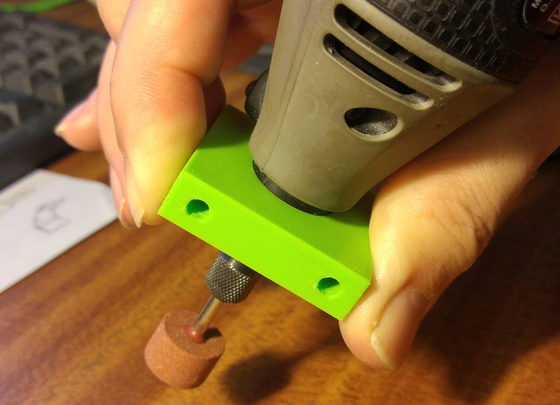
I took the threaded part of Gerald's design, and from it made a block into which I could screw my Dremel 365. It worked very well.
At this point, I did not know what the final design would look like, I just knew I'd need to mount the Dremel in a carrier which would then have to be tilted. In effect, I'm applying Agile principles here - don't put lots of effort into detailed planning before you begin, particularly when the technical risk is high. Try to reduce that risk first by iterating quickly on the key parts of the design.
So I consider the fact that this first stab was a failure to be a success 🙂. It was a failure, because it was immediately apparent that if this block was the only thing holding the Dremal in it's tilted orientation, there would be a very large force on this block, due to the fact that the Dremel's centre of mass was a long way from where this block would be fixed. So large a force that it called into question the reliability of this mounting method. Of course, it was a success because I didn't spend days of design and print effort working on a neat but flawed design.
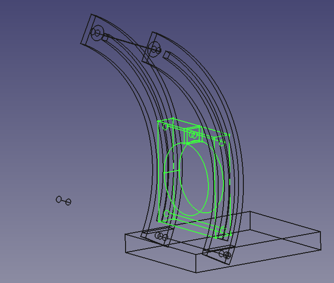
The lesson from the first pass was that the centre of mass of the Dremel was more important than I had realised. If I wanted to clamp it reliably at a certain angle, it would be much better if I wasn't fighting the gravitational tide. In other words, I needed to support the Dremel much closer to it's centre of mass. So, with a bit more conceptual design sketched in, take two, with the holder part ( now wide enough to accept the body of the Dremel ) highlighted :
Yep, this seems to be a good fit :
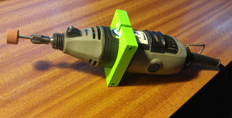
Part of the thinking here is that the top bolt will, in addition to clamping the holder to the uprights, clamp the Dremel in the holder. You would therefore tighten the lower bolt first to set the angle, and then tighten the upper bolt after making any necessary adjustments to the Dremel position. This relies on having just enough give in the holder and the uprights to work.
One thing that should be obvious from the wireframe is the need to decide about which point I am rotating the Dremel. You can see the point I'm using in the wireframe, it's the little floating cylinder. But what does this represent ?
Well, the main thought here was that I wanted to be able to rotate the Dremel without also needing to make an adjustment to the height of the reference surface ( the table, which is not yet envisaged in detail ). In other words, I want to rotate around the most distant point of intersection of the plane of the reference surface with the surface of the grindstone. But this is actually tricky, if you take into account that the diameter of the grindstone is not fixed.
Therefore I've just made a few pragmatic assumptions that seem reasonable, and if I need to raise or lower the table a little I'll live with it. I've defined the centre of curvature to be 115mm from the centre of the groove in the uprights ( i.e. where the holes are in the holder ) along the axis of the Dremel. For modelling purposes, I'm also assuming that this point lies in the centre of the grindstone, but in practice this is controlled by the user when they mount the grindstone in the Dremel and position the Dremel in the holder.

As the diagram illustrates, rotation in the direction of greater angle of incidence ( from primary bevel to secondary bevel ) means that either the reference surface must be lowered, or the blade must be moved further forwards towards the grindstone.
So the next thing is, how much bevel angle am I going to cater for ? This is important, because high bevel angles will move the Dremel both upwards and forwards, which is a consideration for stability of the whole assembly. But there's a sensible limit here - few sharpening applications require or recommend a bevel angle greater than 30 degrees. As long as I can manage 30 degrees, things should work out fine. So just because I can do so easily without making the baseplate really big ( thinking print time here ), I've aimed for 40 degrees.
OK, so now I just need to print more stuff...
and hey, a thing 🙂. It's not complete. It needs the table part, it needs some proper bolts rather than studding, it needs M4 wing nuts, it needs screwing down to something, etc etc.
But, the important stuff works - the Dremel sits there happily without tipping over ( in all positions, and when running ), the holder does act as intended ( bottom bolt fixes angle, top bolt fixes angle and clamps Dremel ), everything is satisfactorily rigid when tightened up. I didn't add the top separator - I thought it might help increase rigidity, but wasn't sure, so didn't make work for myself. As it happens, it appears to be unnecessary.
Although the model tells me this, I verified the maximum inclination using a crude but good enough tool I had lying about :
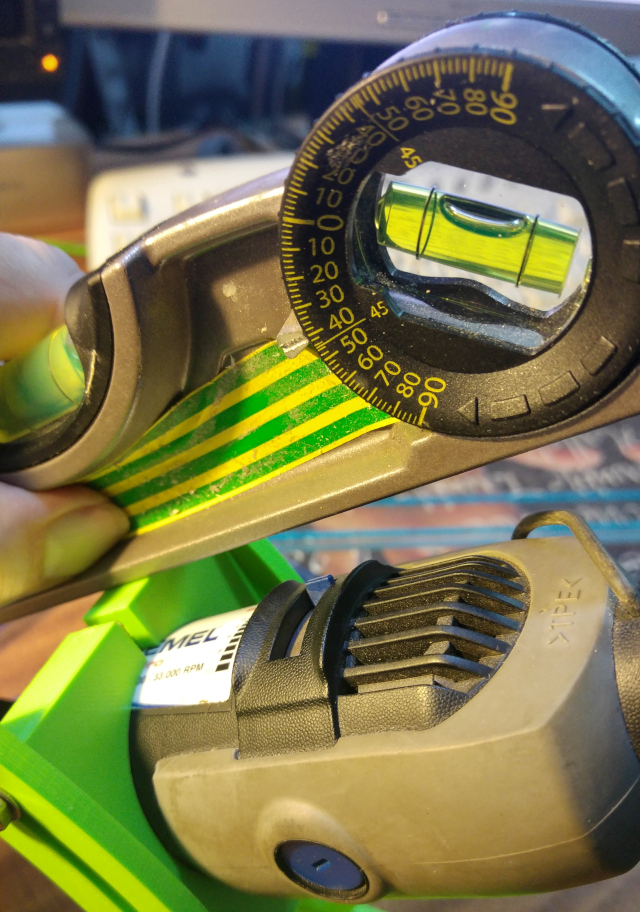
The reading is 40 degrees - easily enough for any reasonable bevel ( which generally won't be more than 30 degrees ).
I can position the Dremel at an angle - now I need to be able to apply the tool to it.
One of the problems I have always had with sharpening knifes using a bench mounted grinder, assuming that I have not ( or cannot ) demount the blade, is that the handle and hilt of the knife interfere with the process because they hit some part of the table or grinder. Jig based devices such as a Tormek or similar can reduce the problem, but my experience is that they do not entirely eliminate it. This is particularly true for curved blades. Even the tang of a demounted blade can be problematic for curved blades.
Therefore I have reconsidered what the table should look like in this light. For my main use case for this particular sharpening tool, namely recurved blades, I am going to want to rotate the knife such that the line of contact with the grinder is normal to the curve ( only by doing it like this will the actual bevel angle/profile bear any relation to the angle between the Dremel and the table ).
Because the curve is a recurve, there will very likely be part of the knife that is positioned forward of the grindstone from the point of view of the user.

So basically, I want as little table as possible ( i.e. the table must not interfere with 'forward' parts of the knife, or with the 'handle side' of the knife ), whilst still supporting enough of the blade to be able to hold it level whilst exerting a small amount of pressure on the grindstone. Also noting that the blade will, very likely, need to be reversed ( i.e. most knife blades have a symmetric grind, not chisel - style ).
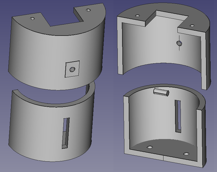
Although I know the issue(s) I think I want the table to address, it's not like I have a requirements document centimetres thick ( it happens... ). I'm never going to have a perfect and complete set of requirements, or I'd be writing them until I was 6 feet under. To learn, we must do. So here is a first pass at a table design. It's a bit different, and there are certainly no guarantees, but hopefully it's useful for learning purposes.
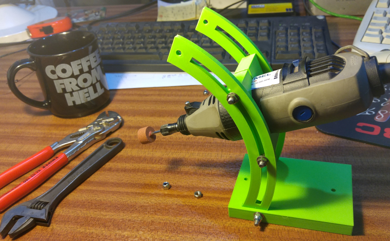
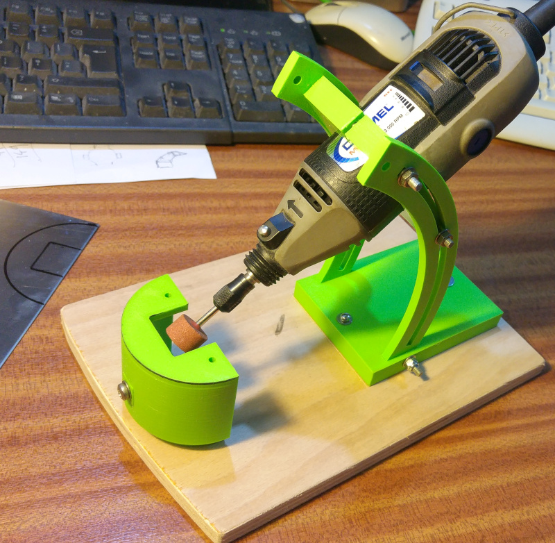
And here is the assembled Prototype #1, screwed down to a bit of scrap plywood in order to allow me to clamp the assembly to a desk/workbench :
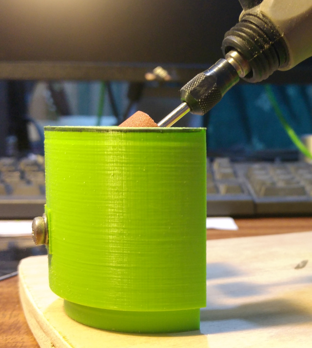
And just for a change of perspective, here's how the grindstone looks at the reference level :
A prototype is for learning, and there are some rapid learnings that I already know will make their way into Prototype #2.
Although there is no problem with side to side movement, or any looseness of the Dremel in the holder, I was overly optimistic when I concluded earlier that things were sufficiently rigid. I did not do a critical test - I didn't apply a downwards force on the grindstone.
When a relatively small amount of pressure is applied to the grindstone, it's enough to cause the grindstone to move in a downwards direction. Not by very much, but enough to change the angle of incidence, and hence is a fault that needs to be corrected.
The root cause of this problem seems to be that the channel in the uprights allows each 'strand' of the upright to bend independently, and since these strands are themselves quite long and thin, the upright bends over because the inner strand tends to buckle. In use, you would not want to be applying much force, but neither do you really want to be worrying about distorting the uprights.
I'll endeavour to fix this by reinforcing the inner strand using a cantilever structure ( just because I want to keep the amount of plastic and the printing time down ).
The root cause of this is that plastic is softer than metal. Doh. It's not a serious problem for testing purposes, but needs to be corrected for a long term solution. In fact, I put a couple of holes in the table just in case I needed to bolt something else to it, and it looks like I should cut a bit of stainless for this purpose.
So now I'll play with this prototype, and see what more I can learn 🙂. Stay tuned if, for some unfathomable reason, you've got this far !
A Dremel is a small tool. It's big brother is called a Die Grinder. These generally ( unless you're Parkside, grrrrrr... ) have a Euro collar, and you can mount things in a 6mm ( Parkside, grrrrr... ) or 1/4 inch collet. The 'things' include a wide array of metal chomping tools, including grindstones.
So it would be really nice to be able to do for my die grinder what I've done for the Dremel. Whether it's feasible ( or even sensible 🙂 ) to design a 3D printed holder/table for this larger device is a topic I'm pondering. Because there are Euro-collar tool holders already out there, it may be that it is simply the table that requires work. Watch this space, as they say !
© Mark de Roussier 2021, all rights reserved.