A BAS315 is a bandsaw, originally sold by Electra Beckum in the 1990's. It was very popular, sold in several slightly different versions, and not always with a Mitre Fence ( accessory no 0910008048 ). If you're reading this, you may have a BAS315 that does not have a Mitre Fence 🙂.
Bandsaws very similar to the BAS315 are still sold today. To make this fence work on your saw, all you may need to do is to tweak the slide to fit your slot, but the 3D print does assume 6mm diameter for the spindle and angle clamp, and so may not work well for narrower width slot.
I have two BAS315's, but the second did not come to me with a Mitre Fence, and this is the problem I needed to rectify.
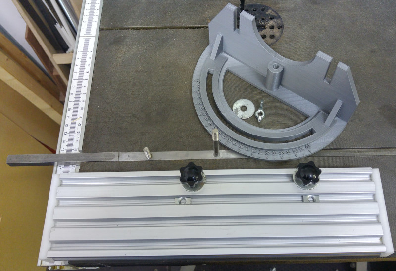
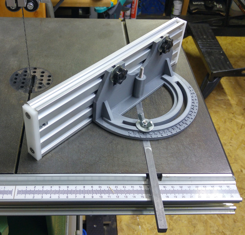
The Mitre Fence has three components - the Slider Bar, the Fence Holder, and the Fence.
This sits in the T slot in the table of the saw. It provides point or spindle around which the Fence holder rotates, and a position at a fixed distance from the pivot point where the Fence holder/Fence assembly can be clamped at a known angle.
One question that taxed me here was that I had no practical way to machine a piece of steel into a T profile. I have a very small mill that can only work easily with softer materials. However in my case the table itself is cast iron ( I think there are some BAS315 with aluminium tables, which would be a different case entirely ), and I was concerned about wear if I used an engineering plastic or aluminium, and I only wanted to do this once.
Later, after I had finished making this thing, I decided I was probably being over cautious - for my hobbyist purposes, involving occasional rather than daily use, Delrin or aluminium would have worked fine for many years.
Eventually I realised that I didn't need to actually cut a T profile. The thing that a T profile does for you is that it allows you to fix a thing in position by pulling something up against the underside of the slot. There is no requirement for this in this case. Indeed, the Mitre Fence must not be fixed in this way, or else it will not slide as intended. And in normal use of the bandsaw, there is no force that will pull the Mitre Guide up out of it's slot.
What is required though is that the bar should be well located in the horizontal plane - it should not wobble or rotate, because any such motion would be amplified at the blade. This is quite easy to achieve, as the vertical part of the 'T' is quite deep. As long as the slider bar fills the width and depth of the slot, with just enough clearance at the sides to move back and forth, all will be well.
So using a nominal 3/8th inch square piece of mild steel ( a very close match to the width of the slot ) I was able to mill off just over 1mm on the top to level it with the table, and that was that. The need to do this came from the fact that my slider protrudes beyond the end of the fence. If it protruded, it would affect the angle of the workpiece. It might be possible to avoid the problem if the fence was positioned over the end of the slider.
The biggest problem making the slider bar was making the countersink for the angle channel clamping screw, so that it cleared the bottom of the T slot. This is the one part of the design that I would probably do differently second time round. I could, by dint of using a suitable studding/knob combination, have just made a tapped hole in the slider and tightened the clamp into that.
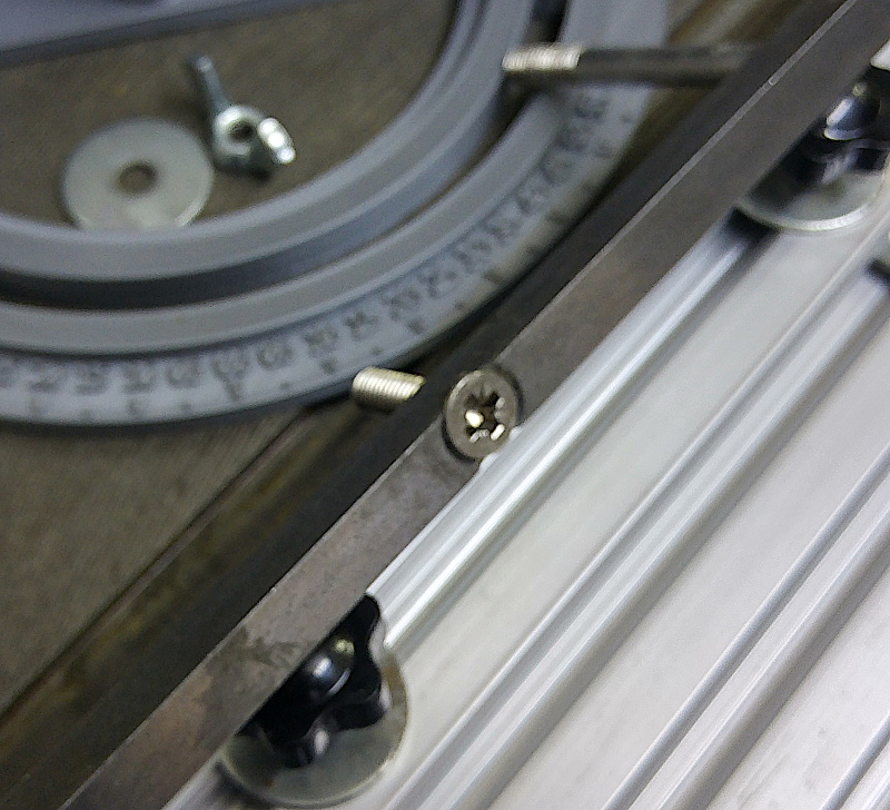
Instead, I needed to countersink the machine screw. This was hard work. I discovered that my snail ( through hole ) countersinks were not up to the job and would just end up spinning in the hole, and I had no decent alternative apart from a 3-flute hand countersink. Even this needed some assistance - I ended up using a small spherical carbide burr to dig out material before making the shape conical with the hand tool. The bolt is epoxied in place.
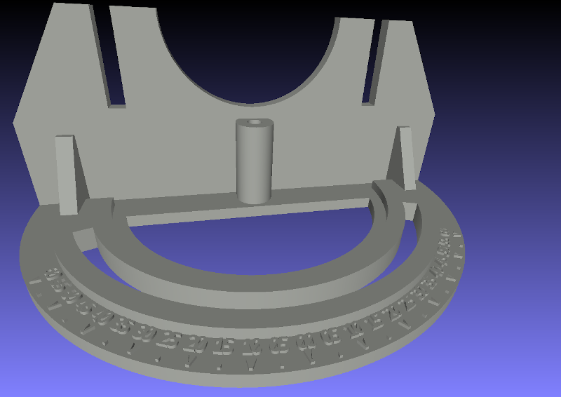
This is the most complex part of the device. It has to rotate around a fixed point on the Slider bar, be clamped at a known angle, and support a Fence whose position is adjustable. Because I have one of the original Mitre Fences, I had a template for the basic design.
If I had access to better milling facilities than I have, it would have been an option to try making this thing out of solid aluminium, but what I have is a 3D printer. I looked at what was available on Thingiverse, just in case any keen BAS315 owner had already solved this problem. There are a small number of mitre fence designs there, but in the end it was simple enough to cook up my own from scratch using FreeCAD.
The design file and STL file are available on Thingiverse.
One important point to note is that the size of the thing is largely dictated by my desire to have legible printed angle values. If you wanted to do this a different way, you might have the option to shrink the size somewhat. However, the design file is not parametric, so you're on your own there, sorry.
There is also a relationship between the size of the spindle hole and angle channel ( 6mm ) and the size of the slider bar. Clearly a narrower slider bar might not work with this size of hole and channel.
I printed mine in PLA on my Prusa i3, which seems to work fine. It has no stringent environmental requirements, and is under no great mechanical strain other than some compression from the clamps.
The size does also mean that there is a risk of warping when printing this. What I've found by experience is that a little warping off the bed at the extremities does not necessarily make the thing unusable - but the section that contains the channel for the clamp does need to be flat.
The Fence itself could, in theory, just be made of a bit of plywood. If you did this, all you would need would be a couple of countersunk machine screws, a few holes pitched to line up with the fence slots, and a couple of wing nuts and washers.
However, overkill being one of my middle names, a more expensive and elaborate solution appealed, which more closely replicates the original. This just involved buying a suitable piece of aluminium extrusion from eBay, identifying a suitable style of nut insert, and sawing off just enough of the thread from the two knobs that they can be tightened without running in to the extrusion.
I put some Delrin 'endcaps' on the extrusion, just because I wanted to have nuts in more than one channel and didn't want to lose the ones that weren't in use.
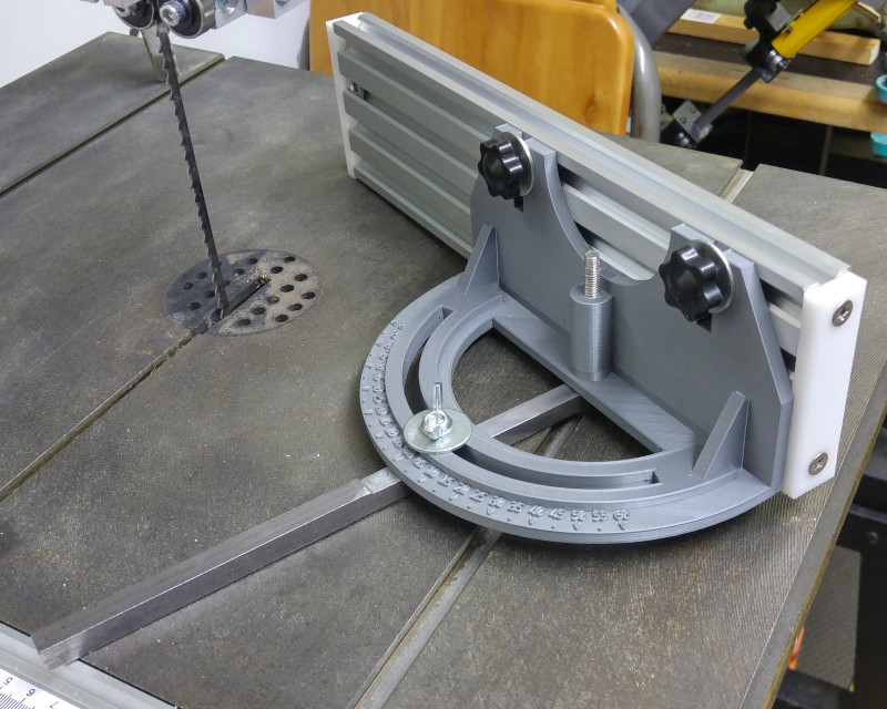
One thing I was unsure of when making this thing was whether I would need to hold down the fence holder onto the slider bar.
One way to do this would be to drill and countersink a clearance hole in the slider bar, and use a machine screw pointing upwards as the spindle. The fence holder design allows a nut to be positioned over the spindle hole, into which this machine screw could be screwed. The fence holder design deliberately prevents this nut from rotating. In practice I would probably have added a washer and some thread lock, because if this ever loosened I would have a machine screw head dragging along the T slot.
However, some tests prior to final assembly suggested that there would be no need for any clamping mechanism other than the wing nut used in the angle channel. And I had been discouraged from countersinking activity by my experience with the angle clamp ( see above ). Therefore the spindle is simply epoxied into a blind 6mm hole in the slider bar ( could have been tapped and threaded, but I didn't bother ), taking great care to ensure it is actually vertical in X and Y, and everything works fine.
Total cost in June 2020 - about £27, excluding the cost of the PLA.
© Mark de Roussier 2021, all rights reserved.